Fundamentals of Switches: Series 3. Illuminated switches
NKK supplies a wide range of illuminated switches, including traditional pushbutton types as well as toggle, tactile rocker and slide switches.
1. NKK's illuminated switches
NKK supplies a wide range of illuminated switches, including traditional pushbutton types as well as toggle, tactile rocker and slide switches.
Switches by series
Pushbutton: FP01, KP, HB, HB2, NP01,UB, UB2, YB, YB2
Tactile: JB, JF, JL
Toggle: B, G, TL, M
Rocker: CW, GW, LW and others
Slider: MS, SS
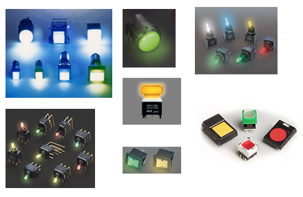
2.Light sources of illuminated switches
Illuminated switches use a range of light sources. Traditionally, standard incandescent light bulbs and neon bulbs were commonly used, although in recent years virtually all switches have transitioned to LEDs. The KB, LB and LMW series from NKK offer a choice of standard bulbs or LEDs.
The table below shows the light sources available in each illuminated switch series.

3.Comparison of light sources
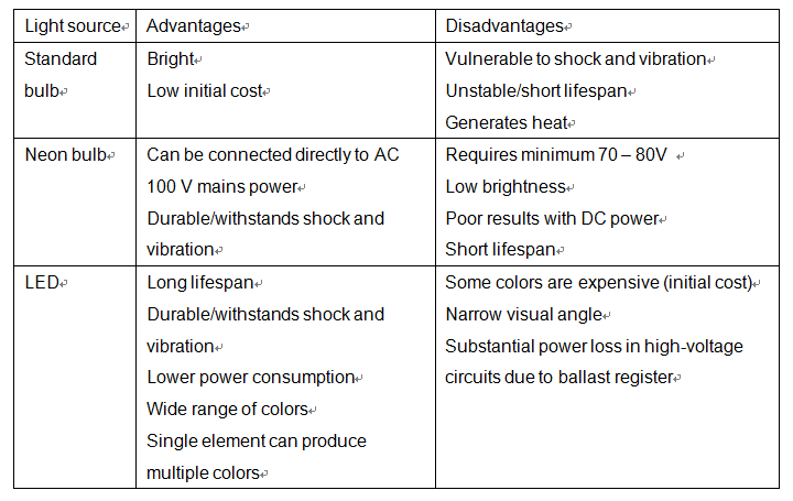
The following table compares standard bulbs, neon bulbs and LEDs, the three light sources most commonly used in illuminated switches.
4.Synchronous and isolated light source
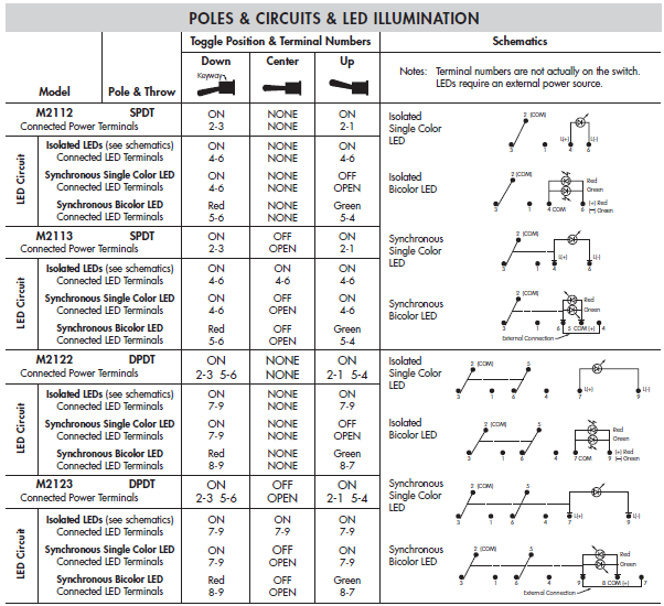
In some switches, the light source is synchronous directly to switch status, while in other switches the light source operates isolated.
M2100 series switches are available in both synchronous and isolated formats.
All other illuminated models are non-synchronous (isolated). Although the isolated format appears more complex, it allows greater freedom of control. For example, the isolated format allows the user to adjust LED brightness via PWM (pulse width modulation).
5.LED circuit
About the LED circuit.
1. The LED is a diode, where current flows in one direction only. The anode (+) and cathode (-) should be connected correctly to avoid damaging the LED.
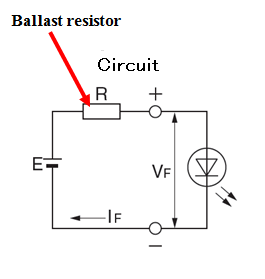
2. A ballast register or constant current diode should be used to prevent excess current in the LED.
3. The LED circuit is normally used with DC power. It can also be used with AC power, together with a rectifier circuit and suitable ballast resistor.
6.Ballast registor
The LED will fail if not used in conjunction with a suitable ballast resistor or constant current diode.
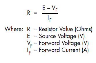
The required ballast register R is given by:
R = (E-Vf) / If where E = voltage of power source VF = LED forward voltage IF = recommended operating current R=current limiting resistance
For example, if the power supply voltage is 5 V, forward voltage 1.9 V and recommended operating current 20 mA, we have R = (5 - 1.9) ÷ 0.02 = 155. Thus the minimum ballast register is 155 Ω.
The permissible resistance power must also be taken into account. From the above example, we have 20 mA x (5 - 1.9) V = 0.062 W, so the minimum rated resistance would be double this value = 0.124 W. When using 24 V, the corresponding figure is 0.884 W, so the minimum rated resistance would be 1 W.
7.Specifications of LED
This is the second time in relation to LED ballast register.
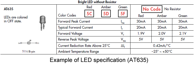
The forward voltage can vary depending on the color of the LED. Red LEDs tend to have a low forward voltage while green and blue LEDs tend to have a higher forward voltage.
A higher ambient temperature reduces the allowable current in the LED. Thus, the ballast register must be determined from the allowable current at the actual operating temperature.
8.LED colours
Let us look at illuminated LED colors.
Monochrome LEDs are available in colors such as red, green, yellow, blue and white.
Popular two-color combinations include red and green, which can display either red or green, or a combination of red and green that appears as amber.
The three-color LED (R/G/B) contains three LED chips (one for each color) and can theoretically produce any color other than black.
White LEDs emit either digital white (synthesized from red, green and blue LEDs) or analog white (generated by a blue LED coated with a yellow fluorescent coating).
In technical terms, LED colors are represented by X and Y coordinates on a chromaticity diagram like the one below.
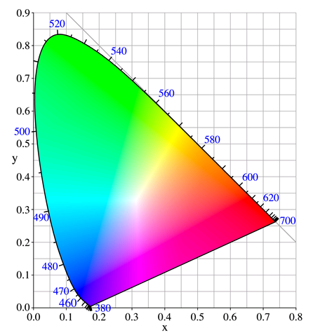
Source: Wikipedia entry for color space

